Altera DE0 Education board
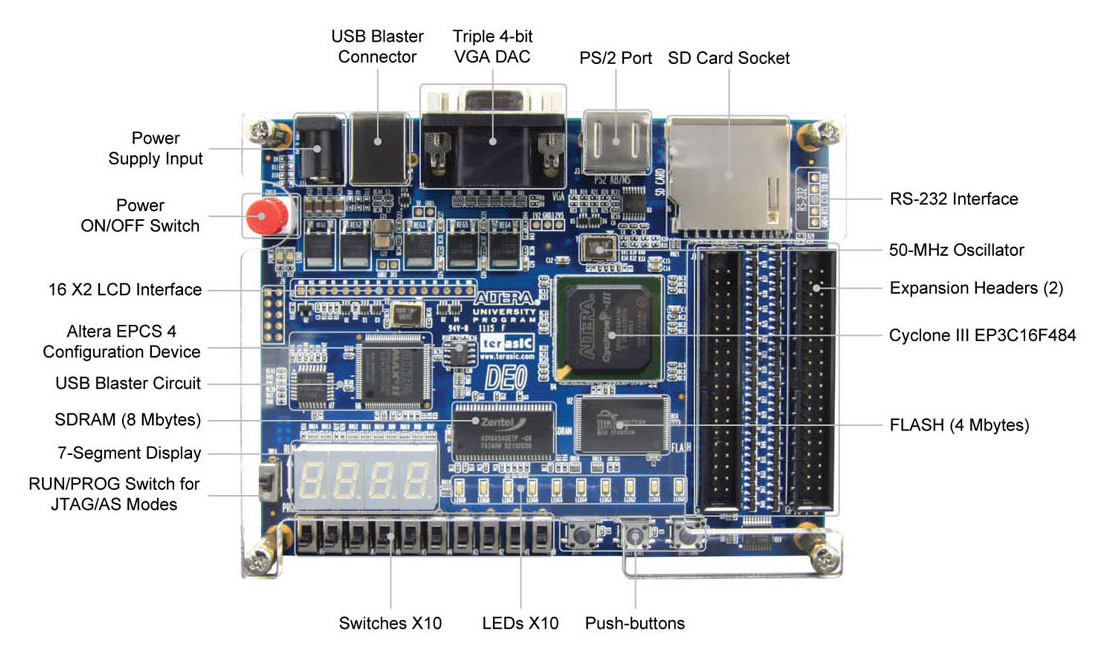
Figure 1:Altera DE0 education board
The heart of the DE0 education board is the Cyclone FPGA EPC3C16F484. The FPGA contains 15408 logic elements, 56 M9K Embedded Memory Blocks, 504Kb Ram, 56 Embedded Multipliers, 4 PLLs and 346 user I/O pins. The DE0 board contains an oscillator which provides the FPGA with a 50 MHz clock signal. The clock signal is connected to pin G21. The DE0 board further contains, among other things, the following components: 10 slide switches, 3 push buttons, 4 7-segment displays and 10 LEDs. All these components are connected directly to the pins of the FPGA, see below.
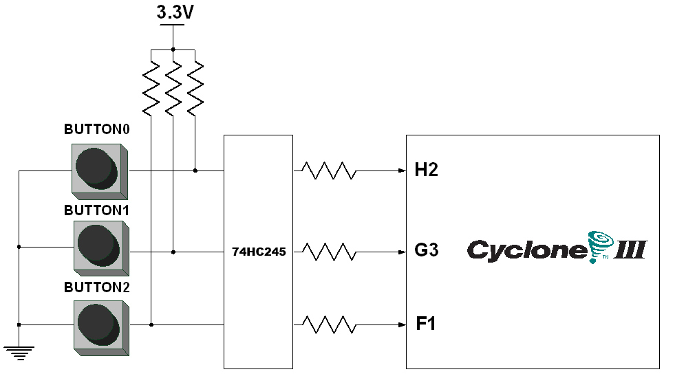
Figure 2:Connections push buttons
The push buttons give a 0, when pressed, otherwise a 1, see Figure 2. The slide switches provide a logical 1 when the slide is standing up, see Figure 3. The LEDs of the 7-segment displays light up when receiving a 0 and are off when receiving a 1, see Figure 4. Finally there are 10 LEDs connected to the FPGA, that light up when receiving a 1, see Figure 5.
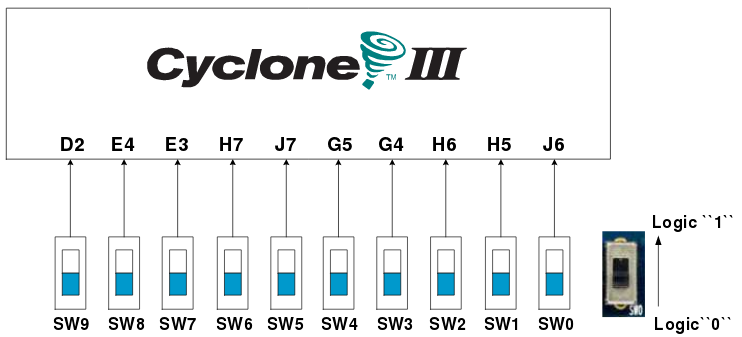
Figure 3:Connections slide switches
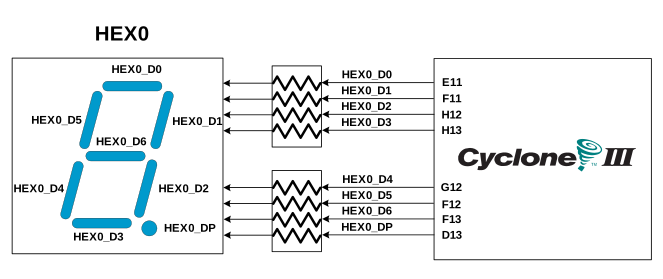
Figure 4:Connections 7 segment display
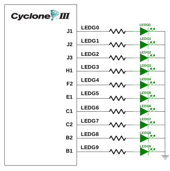
Figure 5:Connections LEDs