Oscilloscope: Tektronix TDS 2022B
Introduction
An oscilloscope is a commonly-used electro technical measuring instrument. It is used to display variations in electrical voltage as a function of time. Whereas in the past analog oscilloscopes were primarily suitable for qualitative measurements (amplitude and shape of a signal), modern digital oscilloscopes can also be used to carry out quantitative measurements (determining the value of a signal). The lab is equipped with the Tektronix TDS 2022B digital storage oscilloscope. This appendix will briefly discuss the operation of this device. For more information, please consult the use manual that is available in the lab room.
Overview
A diagram of the TDS 2022B is depicted in Figure 1. The buttons on the devices are grouped, based on functionality.
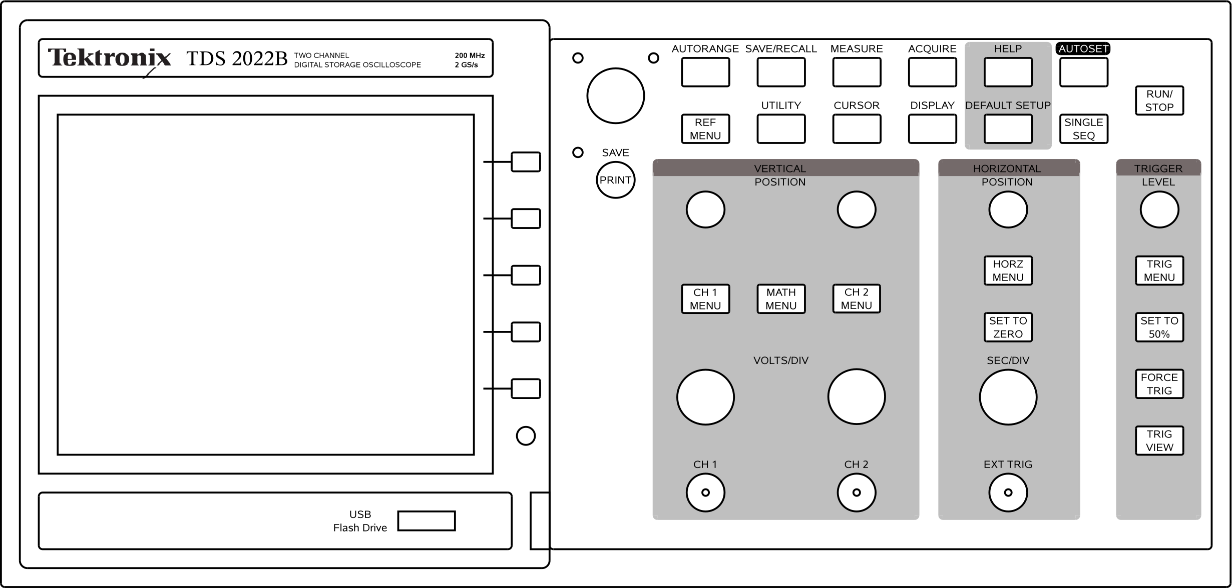
Figure 1:The Tektronix TDS 2022B Digital Storage Oscilloscope.
Basic Operation
The basic operating elements of this oscilloscope are more or less the same as those of an analog oscilloscope. The most important part of an oscilloscope is, of course, the display. The waveforms of the input signals are visualized on this display. The screen is divided into squares, in this case: 8 vertical and 10 horizontal squares. These squares are called divisions, the abbreviation of which is divs. The time is shown on the horizontal axis and the amplitude of the signal on the vertical axis.
Vertical Position
The vertical position group of knobs and buttons are used to modify the vertical scale and position of the waveform. The two large knobs are used to change scale of their respective channels. This is expressed in VOLTS/DIV, the actual setting is displayed in the bottom left corner of the screen, the first channel being preceded by the text CH1 and the second channel by CH2.
The two smaller knobs are used to move the 0 V reference level. This can be useful when displaying two signals simultaneously. The actual setting is shown at the bottom of the screen while turning the knobs and indicated with a small arrow. The channel number is visible on the left of the screen.
CH1 and CH2 menu
The CH1 and CH2 menus are used to set a number of functions for the two channels. A particular channel can be switched on or off by pressing the channel menu button for that channel twice.
The menu comprises the following options:
Coupling (GND, DC, AC): This is used to read out the input signal as GND (handy for adjusting the oscilloscope), DC (this is used to measure a DC component in the signal along with the rest) or AC (this is used to filter out a DC component).
BW Limit (OFF(200MHz), ON(20MHz)): This is used to limit the maximum bandwidth of the oscilloscope.
Volts/Div (Coarse, Fine): This is used to select fine or coarse tuning using the volts/div button.
Probe (1×, 10×, 100×, 1000×): This is used to compensate for the state of attenuation of the probe.
Invert (OFF, ON): This is used to invert the selected channel.
MATH menu
Calculations relating to the input signal can be carried out with the aid of the MATH menu. This menu can be used to determine the difference between and the sum of signals.
Horizontal Position
The large knob is used to change the horizontal scale (time axis). This is expressed in SEC/DIV, the actual value is shown at the bottom right. It is possible to set two different vertical scales, but only a single horizontal scale, so both channels use the same time base setting.
The small rotary knob for the horizontal position is used to horizontally move the 0 s reference level. The SET TO ZERO button can be used to quickly reset the horizontal position.
Trigger Level
The trigger level is used to determine when to start data acquisition and when to display the waveform. The trigger level is a voltage level indicated by a small arrow on the right of the screen. The waveform is shown starting on the intersection point of the trigger level and the 0 s horizontal position. The trigger level can be changed with the small rotary knob.
TRIG MENU
The trigger menu allows you to change trigger settings. The following options are available:
Type (Edge, Video, Pulse): This is used to select the type of trigger event. Usually Edge is the correct setting.
Source (CH1, CH2, Ext, Ext/5, AC Line): This is used to select the source signal. Normally you should only use CH1 or CH2.
Slope (Rising, Falling): Select the type of edge used to trigger.
Coupling (DC, Noise Reject, HF Reject, LF Reject, AC): Allows filtering of the input signal of the trigger circuitry.
SET TO 50%
This button sets the trigger level to the midpoint of the peaks in the trigger input signal.
FORCE TRIG
Force a trigger to start the data acquisition.
TRIG VIEW
While this button is pressed down, the display shows the trigger input signal. This can be useful when trigger coupling differs from the channel settings.
Halting Acquisition and Single Sequence
Data acquisition can be stopped by pressing the RUN/STOP button. This will also freeze the display. Note that the functions of the MEASURE menu, see MEASURE menu, still work.
In order to capture a single-shot signal, press the SINGLE SEQ button. After the input has triggered the oscilloscope, it will automatically halt and show the captured waveform on the display.
AUTOSET
This oscilloscope is equipped with functionality to automatically select the correct settings for the time base, voltage scale and the coupling on the basis of the input signals. This takes place by means of the AUTOSET button. Although this may be very useful, the auto set functionality does not work well if the signal to be measured has a very low frequency.
AUTORANGE
This oscilloscope can also automatically set both the horizontal and vertical scales as well as the vertical signal positions. This is done by pressing the AUTORANGE button. If the auto range function is active, the indicator light on the left of the button will be on. Pressing the button again will turn the auto range function off.
Menus
The various functions of the oscilloscope can be operated by means of menus. If you wish to call up a particular menu, simply press the button with the relevant text. You can then select the settings you want from the menu using the five buttons next to the screen.
MEASURE menu
As already mentioned, a digital oscilloscope can also be used to take measurements. On this digital oscilloscope, the MEASURE menu is used for this purpose. Various measurements can be taken at the same time and the results will be displayed on the menu.
The topmost menu selector button switches between Source and Type. The option selected will affect how the other menu buttons subsequently work. If Source has been selected, the channel to be measured is set using the other buttons.
The Type button selects the type of measurement. The following options are available:
None no measurement;
Freq displays the frequency of the signal;
Period displays the time period of the signal;
Mean displays the average value of the signal;
Pk-Pk displays the peak-peak value of the signal;
Cyc RMS displays the RMS (root mean square) value of the signal;
Min displays the minimum value of the signal;
Max displays the maximum value of the signal;
Rise Time displays the time between 10% and 90% of the first rising edge;
Fall Time displays the time between 90% and 10% of the first falling edge;
Pos Width displays the time between the 50% level of the first rising edge the next falling edge;
Neg Width displays the time between the 50% level of the first falling edge and the next rising edge.
Note that at least one full period of the signal must be visible in order for these measurements to be accurate.
CURSOR menu
Besides the option in the Measurement menu, you can use the cursors from the CURSOR menu. Cursors can be horizontal (voltage) or vertical (time). Vertical cursors can track the active channel and show the voltage level at a specific time instance. They can also be used as a visual reference level, which can be useful to examine the behaviour of a circuit when it is subjected to a sweep input.
The first button in the CURSOR menu can be used to select the type of cursor:
If you select
Off, no cursor will be shown;If you select
Voltage, horizontal cursors will be shown;If you select
Time, vertical cursors will be shown.
The second button enables you to change between different sources:
Ref ARef BCH1CH2Math
The third menu option shows the absolute value of the difference between the two cursors. This option is not selectable and cannot be changed.
The fourth and fifth menu options show the position of the cursors. The active cursor is highlighted and can be moved by means of the general purpose rotary knob on the top left of the buttons.
ACQUIRE menu
The acquire menu can be used to modify the data that is used to draw the signals on the screen. The following options are possible:
Sample: this is the default, it shows directly the sampled data;
Peak Detect: this can be useful when measuring a noisy signal, low amplitude noise is slightly dimmed so spikes are easier to see;
Average: the displayed signal is the average of an adjustable number of samples. This can be useful to filter out noise
In the upper left corner of the screen, an icon indicates the type acquire option.
DISPLAY menu
The display menu can be used to modify the way the signals are visualized.
Advanced Options
This digital storage oscilloscope has some advanced options that can be useful.
Storing Screenshots and Data
The oscilloscope can store and recall data from a USB flash drive. Insert a flash drive into the USB port\footnote{The oscilloscope can only flash drives up to 64 GB capacity, and only when formatted with FAT32. The newer exFat (FAT64) format will not work.} and wait while the oscilloscope examines the drive.
Press the SAVE/RECALL button to setup the action you wish to perform. The following actions are the most useful:
Save Image this option will store a screenshot image in a selectable data format;
Save Waveform this option will store the acquired data points of the selected channel in a CSV spreadsheet file;
Save All this option will store a screenshot, the acquired data points of both channels, and the settings of both channels.
Saving the data will take some time, do not remove the flash drive while the oscilloscope is still writing data!
You can also couple an action to the PRINT button in order to quick access to a save action.
FFT
The oscilloscope also features a low frequency digital spectrum analyzer. This option can be found in the MATH menu by selecting FFT as type of Operation. You can specify the source signal and horizontal and vertical resolution with the VOLTS/DIV and SEC/DIV knobs. The horizontal position knob can be used to select the center frequency on the display.
Probes
Measurement on an oscilloscope are preferably done with a probe. Probes that attenuate the input signal contain a circuit that has to be tuned before the probe is used. Tuning can be done by connecting the probe to the Probe Comp connector. This output will provide a 5 V, 1 kHz square wave input. If the output on the display is distorted, the probe can be adjusted by turning the small screw in the probe (either near the probe tip, or near the BNC connector). Note that probes with an adjustable attenuation factor bypass this circuitry in the position.