Function generator: Tektronix AFG 3021B/C
Introduction
The lab is equipped with the Tektronix AFG 3021B/C arbitrary function generator. This appendix will briefly discuss the operation of this device. For more information, please consult the user manual that is available in the lab room.
Overview
A diagram of the AFG 3021B/C is depicted in Figure 1. The buttons on the devices are grouped, based on functionality.
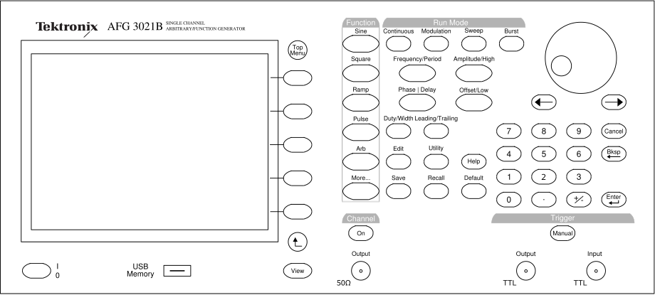
Figure 1:The Tektronix AFG 3021B/C Arbitrary Function Generator.
Run Mode
On the top, there are four buttons grouped as Run Mode. These perform the following functions:
Continuous continuous operation, selected signal is continuously outputted;
Modulation perform AM, FM, PM, of FSK modulation;
Sweep sweep output over a range of frequencies;
Burst output one or more bursts of a signal.
Function
Directly left from the Run Mode group is the Function selection. These allow quick a choice between the following waveforms:
Sine a sine wave with adjustable frequency, amplitude, and phase;
Square a square wave with adjustable frequency, amplitude, and phase;
Ramp a ramp with adjustable frequency, amplitude, phase, and symmetry;
Pulse a pulse with adjustable frequency, amplitude, delay, and duty cycle;
Arb an arbitrary waveform, fully adjustable;
More... select sinc, Gaussian, Lorentz, Exponential Rise or Decay, or Haversine functions or white noise.
Signal Setup
Under the Run Mode buttons are buttons to set up the selected waveform. Each button has two (related) functions, repeatedly pressing the button will alternate between the functions.
Frequency/Period select the frequency or period of the signal;
Amplitude/High select the amplitude or the high voltage level;
Phase Delay select the phase shift or the delay;
Offset/Low select the offset or the low voltage level.
When the Pulse waveform is selected, two additional buttons are available:
Duty/Width select the duty cycle or pulse width;
Leading/Trailing select the leading and trailing time.
Pressing one of these buttons highlights the corresponding setting on the screen. The value can now be changed by either typing in the numerical value on the keypad and pressing Enter to confirm, or by using the general purpose rotary knob. The arrow keys directly under the general purpose knob move the cursor and thus the digit changes when turning the general purpose knob.
The screen shows also shows a preview of the signal annotated with all the important voltage levels and frequencies. These levels are only valid when the output impedance is properly set up, as described in Section \ref{sec:app.function_gen.output_imp}.
Additional Signal Setup
The buttons directly next to the screen are context-sensitive and are used to modify additional signal parameters. Changing the parameters is identical as described in Section \ref{sec:app.function_gen.signal_setup}.
Output and Output Impedance
The output of the generator is the leftmost coax connector labeled Output. The amplitude settings on the generator are only valid when the value of the load impedance is properly configured. By default, the load impedance is assumed to be 50 Ω. The input impedance of, for example the oscilloscope, op-amp inputs and almost any digital IC input is very high. In order to have the actual voltage levels match the settings on the function generator, the output impedance has to be changed to high impedance. You can use the following steps to set the output impedance to high impedance.
Top Menu (this is the upper button next to the screen),
Output Menu,
Load Impedance,
High Z.
The lower button can be used to return to the main screen.
Note that the output settings are only valid for a fixed load impedance; if the load is highly variable, make sure to verify the actual output on an oscilloscope or use a buffer circuit.
The output signal is enabled or disabled by pushing the On button in the block Channel just above the output connector.