Soldering
Introduction
Soldering is the process of using molten metal, usually tin, to make an electrical connection between two conductors with a low resistance. Being able to solder is important for electrical engineers because it allows you to build and test your ideas. Unsurprisingly, you will use this skill in many future labs and courses.
In the industry, where circuits are often mass-produced, the soldering process is largely automated. Having your circuit be assembled in a factory, however, is often too expensive or time inefficient to be worth it. For these cases manual soldering is the way to go. While there exist many soldering techniques, in this chapter we stick to basic manual soldering with a soldering iron and solder.
Equipment
Solder is a metal alloy which usually consists of 60% tin (Sn) and 40% lead (Pb), called leaded solder, or 96% tin and 4% silver (Ag), called lead-free solder. In the lab we use lead-free solder.
Leaded vs Lead-free solder and RoHS
Since July first 2006, the Restriction of Hazardous Substances (RoHS) applies. This states that certain hazardous substances may no longer be used in electronic devices. One of the prohibited substances is lead. For industrial applications, leaded solder may no longer be used. Instead, lead-free solder based on tin and silver (96% tin and ~4% silver) is used. While leaded solder normally has a melting point of about 185°C, lead free solder has a melting point of 221°C. Due to the fact that a higher melting temperature is needed a soldering iron should be set 30-40°C higher than for tin/lead solder. Please note that the the introduction of the RoHS policy also implied that the components had to be made suitable to withstand the higher temperature and not be destroyed.
Practically, soldering with lead-free solder is more difficult than soldering with leaded solder. Nevertheless, we prefer lead-free solder for environmental reasons.
A soldering iron, such as the one shown in Figure 1 is a hot metal rod with a tip. It lets you melt the solder and heat up the metal that you want the solder to attach to. When soldering electronics, a 30 W soldering iron is sufficient. For large components or when soldering on a large surface, a soldering iron with more power is needed. Temperature-controlled soldering irons are useful but not essential. If a soldering iron delivers too much power or becomes too hot, it can destroy the component or the circuit.
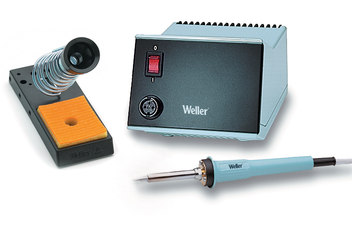
Figure 1:A soldering station with a holder and cleaning sponge.
How to Solder
Before you begin with soldering, the tip of the soldering iron must be at the correct temperature and cleaned. For a soldering iron without temperature display, an indication of the correct temperature is when the solder immediately melts if you hold it against the tip. If black crusts is present on the tip, first clean it with a wet sponge.
Before you can make a solder connection, both components should be cleaned well, otherwise the solder will not properly flow, or will create a bad connection. If necessary, clean the components by sanding them lightly with fine sandpaper or scratch them with a knife. You actually never have to do this when soldering new electronic components; when using older components, it may be needed.
Tinning and soldering stranded wires
Before soldering a wire, it must first be cut to length and stripped. Use wire cutters or sharp scissors to cut the wire cleanly. To remove the insulation, use a wire stripper set to the correct gauge — strip about 5–8 mm from the end. If a wire stripper is not available, the wire cutters can be used by scoring around the insulation at the desired point without cutting through to the strands, then pulling the cut piece off. Alternatively, a sharp knife can be used. In both cases, take care not to nick the copper strands, as this weakens the wire and causes a poor joint.
Stranded wires (wires made up of multiple fine copper conductors twisted together, as opposed to a single solid conductor) must be tinned before soldering, because the individual fine strands will otherwise not bond reliably. To tin a stranded wire, first twist the fine copper wires together. Then hold the wire against the tip of the soldering iron, and touch the solder wire to the wire itself — not to the iron tip. When the wire is hot enough, the solder will melt and flow between the strands. Add enough solder so that the wire is completely filled. Once fully tinned, remove the solder wire and soldering iron. Figure 2 shows the correct result.
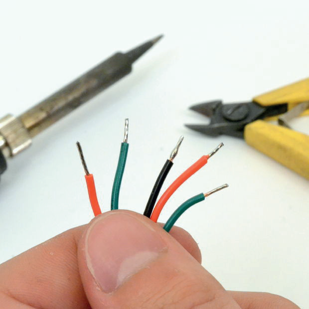
Figure 2:Tinned wires. Source: Instructables CC-BY-SA
To join two tinned wires, bring them together and keep them steady, then press the soldering iron against both. Once hot enough, add a small amount of solder at the joint. If the solder neatly flows between the parts, remove the iron. As with any joint, the parts must not move while the solder cools.
When joining solid wires together, or soldering a wire to a surface, pre-tinning is not strictly necessary — both parts can be heated and joined in a single step. However, tinning each part first can make soldering easier, particularly when one surface is difficult to heat evenly or when a surface is not perfectly clean.
Soldering components to a PCB
New electronic components are usually already tinned, and PCBs are delivered with a solder lacquer that promotes wetting (the ability of molten solder to flow and adhere evenly to a surface); you therefore do not need to pre-tin component leads.
To make a solder joint, place the lead through the hole and press the tip of the soldering iron firmly against both the lead and the copper pad at the same time. Remember that a small amount of solder already on the tip can help with heath transfer. Touch the solder wire to the joint — not to the iron tip — and let a small amount of solder flow in; it will start to flow when both parts of the joint are hot enough. With a good joint, you will see that the solder has ‘crept up’ along the lead due to the cohesive force (see Figure 3). Smoke indicates that the flux in the solder is active and evaporating; once the joint is made, remove the iron and allow it to cool without disturbing the parts. If the joint does not look right, re-heat it with the iron, add a small amount of new solder if needed, and allow it to cool again.
With old components, it is often advisable to tin the leads first, because the solder already on them may have become dirty and greasy. If the solder after heating does not flow properly, this is a sign that the surface is not clean; re-tinning or first cleaning as described above is the only solution. A solder joint with dirty connecting wires results in a poor, unreliable connection that may fail at any point in time.
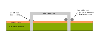
Figure 3:Schematic representation of a correct and incorrect solder connection.
Other sources for soldering instructions
On learn
Additional tips from Popschool Maastricht (translated into English)
First, melt some solder to the tip of the soldering iron and then heat the component(s) which you want to solder, by pressing the tip against the component. Apply the solder to the heated part and let some solder flow out, but not too much! If the solder on both parts has flowed out nicely, remove the soldering iron. Keep the two parts at rest for a few seconds. If the solder becomes dull, you can release the components. If the items are moved during cooling, or if the solder looks gray, re-melt the solder with the tip and let it cool down, otherwise you have a weak connection with small (often invisible) cracks in it.
Tin both parts separately first.
Solder fast and let the parts not become too hot. Insulation can melt or carbonize and cause a short circuit without being directly visible. Many electronic components (particularly semiconductors such as transistors and ICs) are vulnerable to heat and can therefore fail.
If you were to solder components susceptible to heat, you can dissipate some of the heat by holding a wire with pliers.
A desoldering pump can be useful to suck away excess solder. There is also a desoldering wire, with which you can suck melted solder. Cut off and discard the used wire.
Note: Do not burn your fingers on a hot soldering iron or hot work pieces.
If you are working with very sensitive electronics, they can be damaged by high voltages caused by static electrical charge. To prevent this, there are special wristbands to drain this charge to earth. In certified laboratories, wearing these wristbands is mandatory.
Check connections with a multimeter to see if there is no short circuit. Set it to the lowest resistance measuring range. Some multimeters have a connection tester with a beep. To test whether the insulation between terminals which must not be connected is correct, choose the highest resistance range.
With a magnifying glass, you can take a better look to see if a soldered connection has, for example, a small tear in it.
The tip of the soldering iron must be cleaned by removing it along a damp sponge. Then re-tin it with solder. A soldering station often has such a sponge. Note: Do not use sandpaper or sharp objects to clean the bolt! Most good soldering stations today have a “long life tip” which is provided with a coating against oxidation. If you damage it, your fine soldering tip has become useless!