Components
During the Linear Circuits A lectures you learn how to analyze the behavior of circuit models, but not how to build the circuits themselves. This appendix, together with the next one on Soldering, fills that gap by treating the very basics of circuit assembly.
Connections
This section is about physical components that transport voltages and currents from one point in 3D space to another. While any electrically conductive material is able to do this, it is common to use wires or cables, which are specifically made for this purpose.
Wires
Wires are elongated flexible pieces of metal. They are usually coated with an electrically insulating layer to prevent unwanted electrical connections. This insulator can be stripped off the wire with a wire stripper.
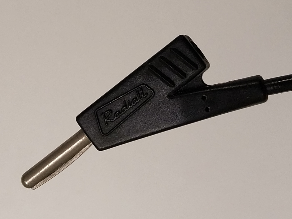
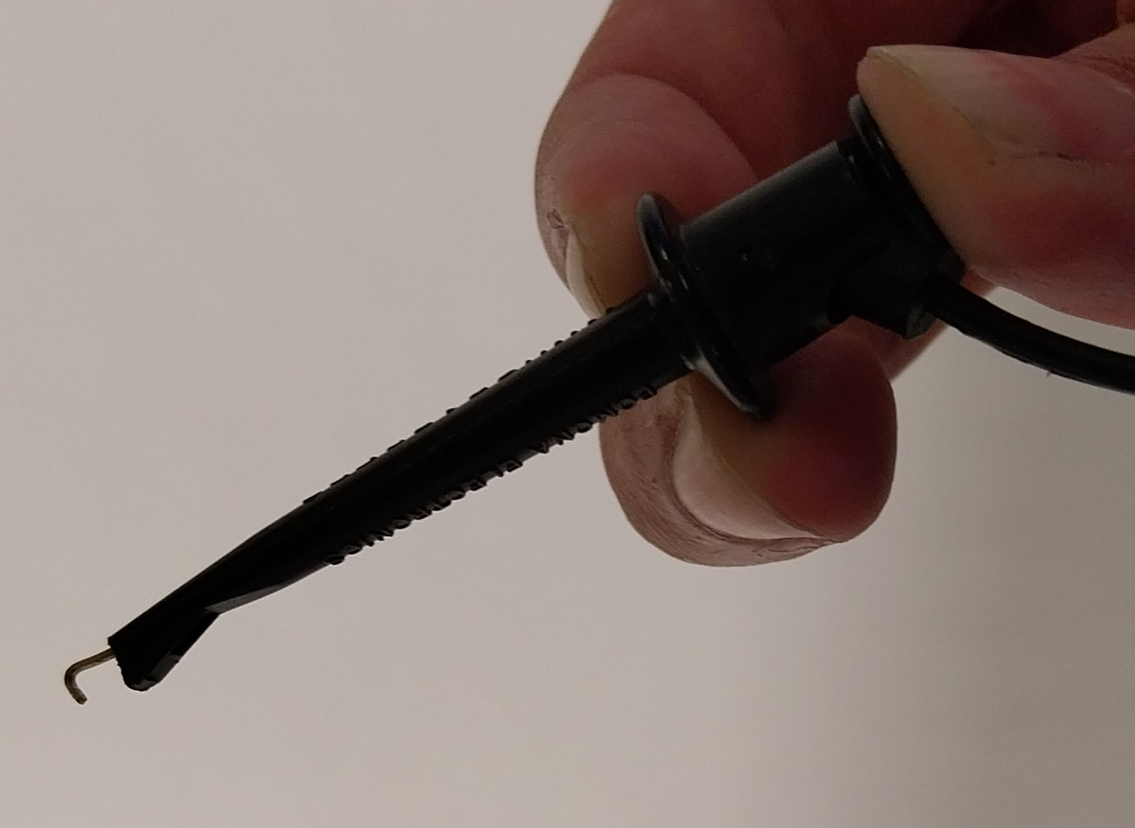
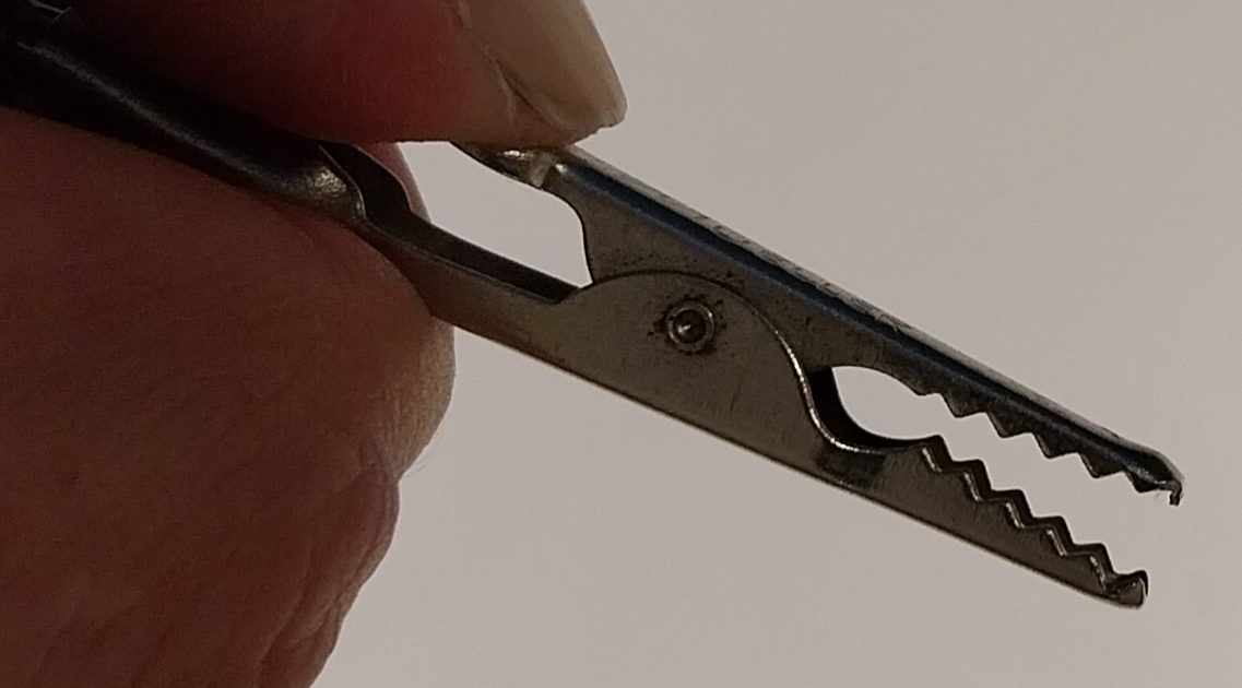
In the Tellegen Hall you can also find reusable wires. Their ends have a specific shape called a connector that allows you to make reliable electrical connections without needing to solder. Here follows a list of common wire connectors and their names.
Cables
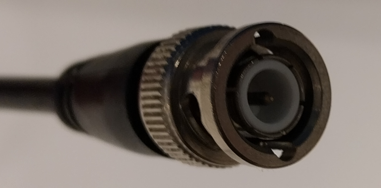
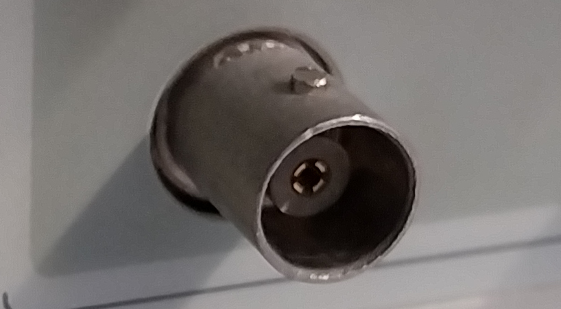
Cables are bundles of one or more wires. There are too many types to list. You are probably already familiar with a few (e.g. USB or ethernet cables). The most common cable you will see in the lab is the coaxial cable - or coax for short. Coaxial cables can come with many different connectors, but in the lab you will only find ones with a BNC connector.
Coaxial cables have 2 wires: a regular wire surrounded by a metal sheet with the shape of a hollow cylinder that acts as its own wire. This sheet serves not only as a return path for the current, it also shields the signal cable from external noise and interference.
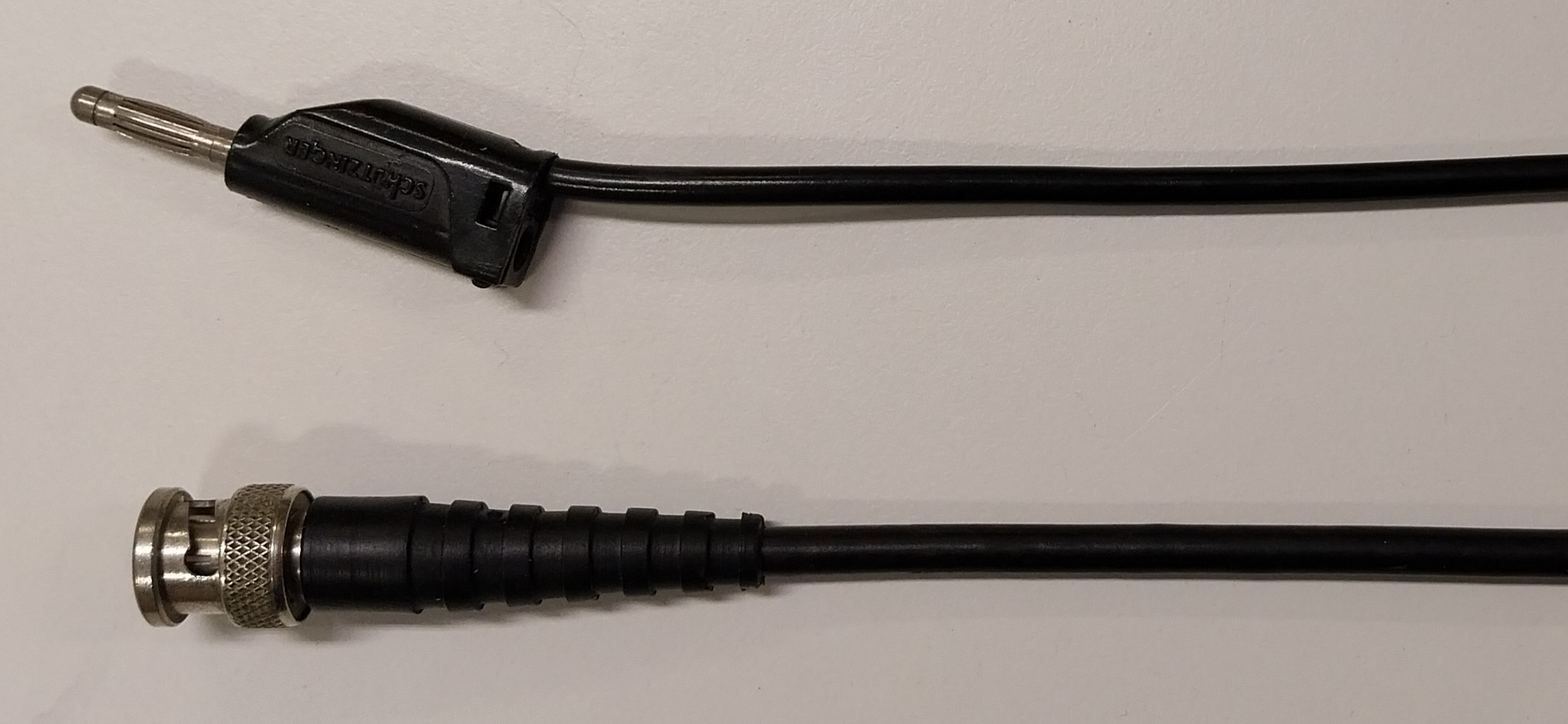
Figure 4:A reusable wire with a banana plug (top), and a coaxial cable with a female BNC connector (bottom).
Electric Devices
This section is about physical components that react to or generate voltages and currents. Only devices that are relevant in the context of the Linear Circuits course are listed here.
Resistors
Resistors come in many forms. A few common types are listed below. In the lab we use axial resistors most of the time.
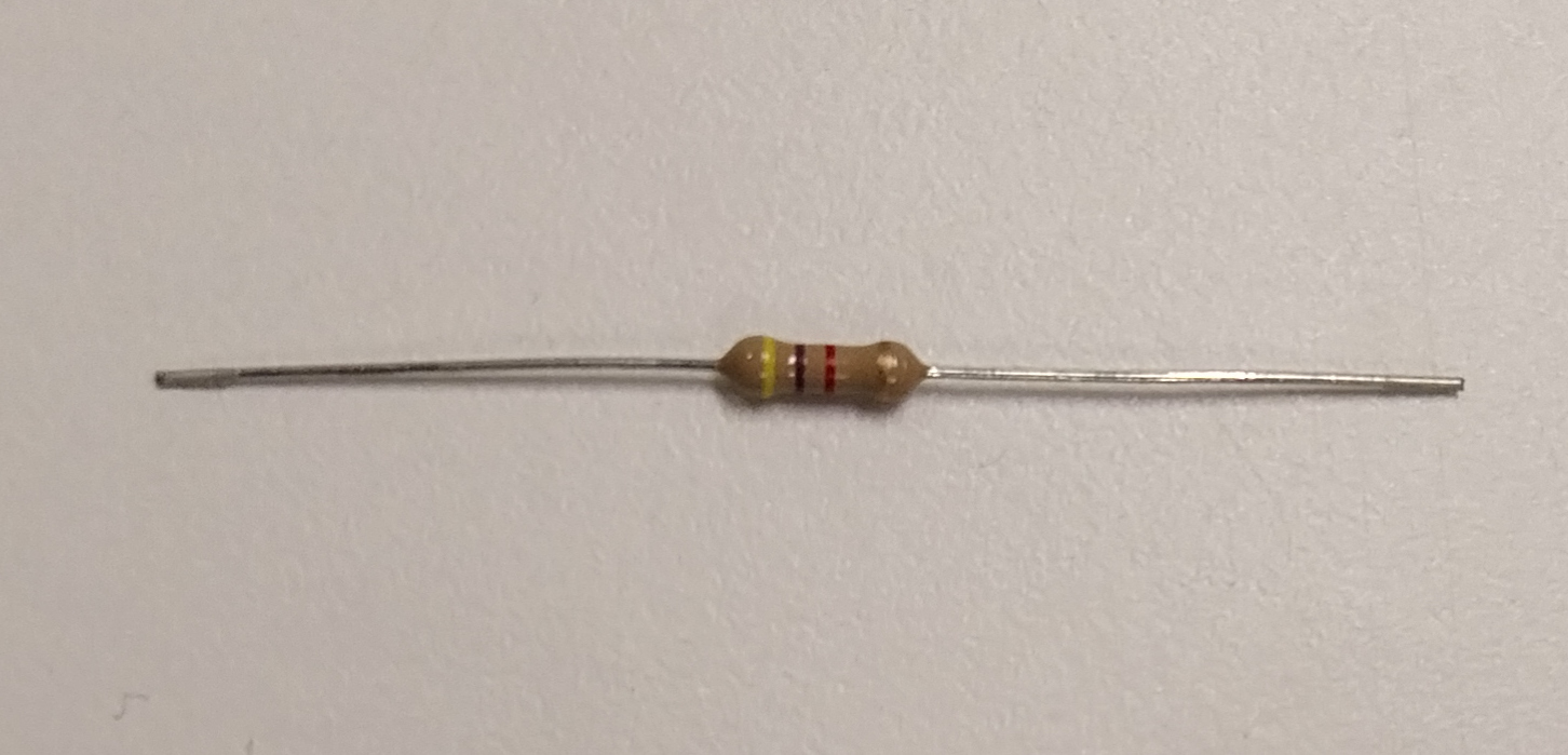
Figure 7:Axial resistor
Not every resistor value can be found on the market, because it would be very inconvenient and costly to manufacture and sell so many different values. Instead, almost every manufacturer adheres to a set lists of values dictated by international standards that is called the E series.
The 7 official E series are E3, E6, E12, E24, E48, E96, and E192, which come with manufacturing tolerances of 50%, 20%, 10%, 5%, 2%, 1%, and <0.5% respectively. For the E3 series, any resistor value you want is always at most 50%, i.e. the tolerance, away from a value in the series. The same is true for the other series. The higher the series number the more accurate but also the more expensive a resistor is.[1]
The value and the tolerance of a resistor is usually printed on the resistor itself, or it is represented by a series of colored rings. Nowadays it is often more convenient to measure the value of a resistor with a multimeter than to decypher the color code - especially if you are colorblind.[2]