Tutorial QuestaSim
Overview
QuestaSim is a popular software tool that is used to simulate and debug hardware descriptions written in HDLs like SystemVerilog (SV). The goal of this tutorial is to learn how to use the most important basic features of QuestaSim. We will use files from labsDSA.zip (found on Brightspace). Download this file and extract it in a directory of your choice.
On Brightspace (under Resources > SystemVerilog Simulation > Install QuestaSim). it is described how you can use QuestaSim on your own PC. If you’re working on the PCs in the Tellegen Hall, QuestaSim will come pre-installed. You can find it under Start > QuestaSim-64 10.6g > QuestaSim. By opening the program, you should see a window like the one in Figure 1.
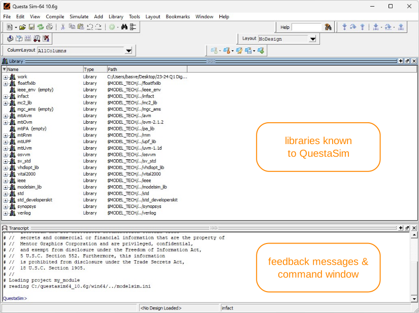
Figure 1:The main window of QuestaSim
You can see two stacked windows. The Library window contains a list of HDL libraries that are understood by QuestaSim. The Transcript window functions as a command terminal. You can type commands here for the program to execute, and the program will give you feedback messages. Note that you don’t have to use the Transcript window. Most commands can be given to QuestaSim via the tabs on the top of the window (e.g. File, Edit, View, etc.) instead.
Project Set-up
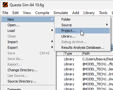
After extracting the labsDSA.zip, go to labsDSA/tutorial_questasim to find the SV files for this assignment. To add these files to QuestaSim, we need to make a project and add the SV files to this project. In QuestaSim, go to File > New > Project. Select as Project Location the directory labsDSA/tutorial_questasim and give the project a Project Name (e.g. “tutorial_questasim”).
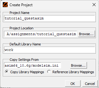
After clicking OK, an “Add Items to the Project” pop-up will appear. Click “Add Existing File” and select the files my_module.sv and my_module_tb.sv. Click OK, and then close the window.
Editing & Compilation
View the contents of the file by right-clicking on the file name my_module.sv and selecting Edit in the pop-up menu, or by clicking twice on the name. QuestaSim will open the file in a new tab.
Before we can simulate my_module, we need to compile it first. During compilation QuestaSim checks if the syntax of the file is correct, and makes a model for the simulation of the circuit. To compile a file, right-click it and select Compile > Compile Selected.
Since the file we provided you with contains a syntax error, a red cross will appear in the Status tab right of the file name. Double-click the red cross, and a pop-up will appear with a description of the error. The error message says that the compiler was scanning the code, and found the keyword endmodule on line 10, while it expected to find a ; before that. Try to infer this from the error message yourself. After that, add the missing ; and save the file. The red cross should change into a blue question mark. This means that there have been uncompiled updates to the file. Recompile the file, and a green check mark should appear, indicating that the compilation was successful. Also compile the file my_module_tb.sv.
Running a Simulation
Go to the Library tab and click the plus sign to the left of the work library (see Figure 4). Right-click my_module_tb and select “Simulate without Optimization”. The QuestaSim window should now look something like Figure 5.
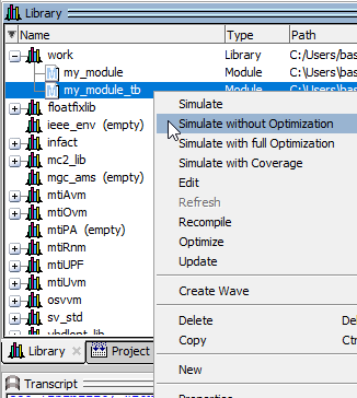
Figure 4:Start the simulation.
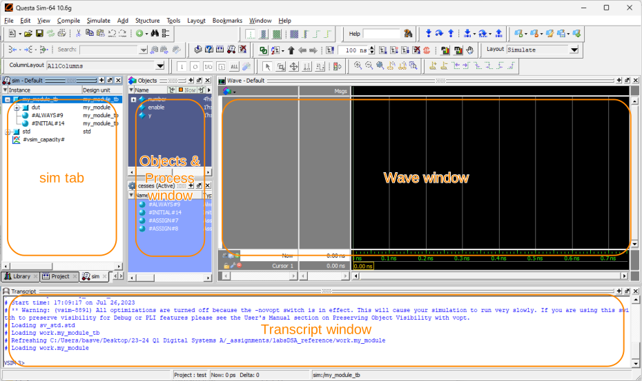
Figure 5:The simulation window of QuestaSim
Four new windows appeared: sim, Objects, Processes (Active) and Wave. The sim tab shows the module hierarchy of your design. The hierarchy in this tutorial seems simple enough: the module my_module is included in (is a sub-module of) my_module_tb. However, the complete hierarchy looks more like shown in Figure 6. The grey blocks are called “processes”. These are the so called “leaves” of the tree diagram of the hierarchy. Processes are blocks of code that add functionality to a design. In contrast, modules merely combine and connect processes (and/or other modules) with each other. The name of each process contains the type (assign, initial, always) and the line number at which it appears in your code. If you haven’t heard of some of these process types yet, you’ll learn about them in one of your next lectures.
The sim tab allows you to navigate the design hierarchy. If you click on a module or process, the internal signals of those units appear in the Objects window, and get highlighted in the Processes window. In the Objects window you can select certain signals, right-click them, and add them to the Wave window. Understanding, and being able to navigate these windows will make your life much easier once you start simulating or debugging larger systems!
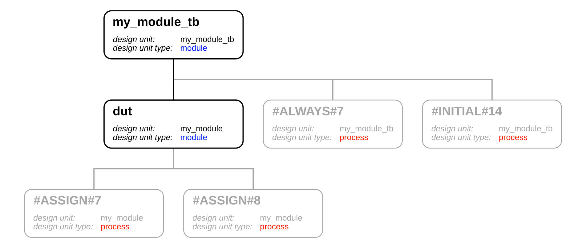
Figure 6:Hierarchy of the simulation made by QuestaSim.
Click on my_module_tb in the sim window, select all signals that appear in the Objects window, right-click them, and select “Add Wave”. The signals should now appear in the Wave window as shown in Figure 7. Now, to run a simulation, go to the Transcript window at the bottom of the page, and type “run 320 ns”. Press enter, and if everything went correctly, you should see waveforms in the Wave window. Click on the Wave window, and press F (zoom fit) to view the entire simulation. It should look like Figure 8.
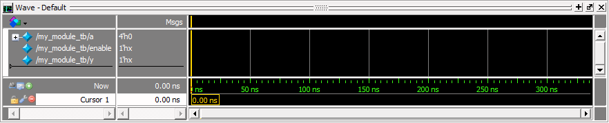
Figure 7:Wave window with signals defined in my_module_tb.sv
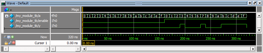
Figure 8:Simulation result, zoomed out to fit the complete simulation.
And there we go! You now know how to simulate SystemVerilog descriptions of digital circuits in QuestaSim!