Week 1.1: Soldering & DC Measurement
1Introduction
In this lab you will assemble a basic circuit on a prototyping board, and perform voltage, current, and resistance measurements on this circuit. In the process you will gain experience with soldering and using common lab equipment.
Study Goals
After doing this assignment, you should be able to:
Assemble a basic PCB with reliable solder joints
Apply in practice the concepts of voltage and current
Use a multimeter and voltage source
Explain measurements using Ohm’s law, equivalent resistance, and Kirchhoff’s laws,
Explain the influence of non ideal meter impedance.
2Theory
2.1Ohm’s law, equivalent resistance, and Kirchhoff’s laws
For the assignment below, you will need to apply some theory that will be treated in Week 1.2: Ohm’s law, equivalent resistances of resistors in parallel and in series, and Kirchhoff’s laws on voltages and currents. However, you will probably remember them from secondary school, and the assignments won’t go very deep. However, if needed, please consult your book on Linear Circuits.
2.2Non ideal input resistance of a multimeter
There is a deviation between the ideal measurements and the actual values. This is due to the fact that the instrument becomes a load to the system. For example, the input of the oscilloscope (which you will use in a later lab) has a finite resistance (1 MΩ) and will draw some current from the source that may cause a measurable drop. Also between the wires of the oscilloscope an undesired (parasitic) capacitance exists that, above a certain frequency will start to dampen the signal and influence the measurement.
Voltmeters have an input resistance that is finite. This means that, unintentionally, they draw some current from the circuit to which they are connected, as shown in Figure 3.
In the same way, real ammeters have an input resistance that is nonzero (note: the ammeter, taken from Ampere Meter, is an instrument to measure the electrical current in a circuit); see Figure 4. This means that the current they sense causes some undesired voltage drop across the terminals that will actually change the current that flows.

Figure 3:Equivalent circuit of non-ideal voltmeter. A larger is better.

Figure 4:Equivalent circuit of non-ideal ammeter. A smaller is better.
In this assignment you will apply Ohm’s law to investigate the non ideal input resistance of a multimeter. You will work with a modern digital multimeter.
Most instruments have various ranges, which makes it possible to measure with sufficient resolution. Please use an instrument within its range! A voltage or current out of range can blow a fuse or even destroy it.
3Assignments
3.1Soldering stranded wires
The goal of this assignment is to connect all strands of a stranded wire with solder. Soldering vices are available for holding the wires steady during this assignment. If none are free, you can improvise: a fellow student can hold the wires, or you can weigh down the insulated sections while keeping the stripped ends raised off the table.
Take two stranded wires of about 10-20 cm each.
Strip about 1 cm of insulation from one end of each wire.
Twist the exposed strands together firmly.
Tin both stripped ends.
Solder the two tinned ends together to form a single joint.
Have the result checked by the teaching assistant before continuing.
You may check yourself by also stripping the other ends and using a multimeter to check for a low resistance.
3.2Soldering on a prototyping board
In this part of the assignment, you will build a circuit that is often referred to as a five-bit R-2R ladder network[1]. It can be found in e.g. digital-to-analog converters, where it is used to convert the ‘1’-value bits in corresponding portions of 1/2, 1/4, 1/8 .. of the reference voltage Vref and add them together to get the analog output voltage. You will use it in the multimeter assignment later. Please assemble one PCB per student.
Collect 16 resistors of 100 Ω with a maximum power rating of 0.25 W. You can find them in the component room in the Tellegen Hall.
Prepare the initial circuit’s configuration according to Figure 5. Make sure that you make connect the resistors to the prototyping board exactly as shown in Figure 3. To connect multiple resistors, you must create the so-called “Islands of solder”. By making sure that the soldering tin is hot before applying it to the board the tin will stick to metal better, and form a clean joint.
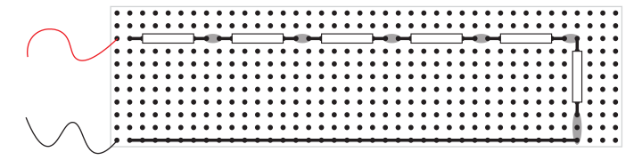
Figure 5:Initial circuit with six resistors. Note: This circuit is still not the full configuration of the ladder network.
Set your Fluke 117 multimeter to the resistance measurement mode (Ω). Measure the resistance between the red and black wires.
Add the resistors from 1 to 10 as it is shown in Figure 6. What is the value of the final resistance (between the two terminals)?
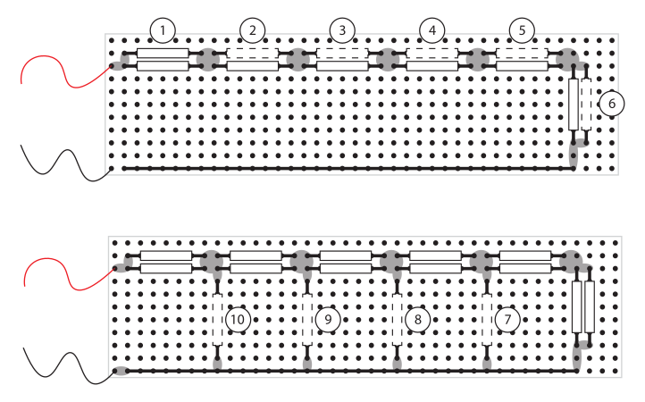
Figure 6:Completion of the initial circuit to the full ladder network.
Using a pencil or a marker with a white tape, write your name on your PCB.
Let your soldering work be verified by the tutor or teaching assistant.
3.3Ladder network characterization
Why does this damage the meter?
When the multimeter is set to measure current, it internally acts almost like a plain wire. It has a very low resistance, so that it disturbs the circuit as little as possible while the current flows through it. This is fine as long as the meter is inserted in series, i.e. in the current’s path, where something else in the circuit (a resistor, a source’s internal resistance, etc.) limits how much current can flow.
If you instead connect the meter across two points, as you would for a voltage measurement, but the meter is still set to current mode, you are connecting that near-zero resistance directly between two points that may have a real voltage difference between them. This creates a short circuit through the meter, causing a large current to flow, which will most likely blow the meter’s internal fuse or, in the worst case, destroy the meter.
In short:
voltage mode is high-resistance and safe to connect anywhere (but provides a wrong measurement when connected in series)
current mode is low-resistance and safe only in series.
Clear your workbench of all metal clippings and loose parts.
Connect your ladder network from the previous assignment to a voltage source of 5 V. As a power supply, select the Farnell TOPS on your bench, and use the 0/5 V output. More precisely: connect the red wire to the red ‘’ terminal of the power supply, using a cable with a banana jack on one side and a clip on the other side. Connect the black wire to the black ‘’ terminal of the power supply, and turn on the power supply.
With a digital multimeter, select the voltage measurement setting and the correct range, and measure the voltages on all nodes numbered 1 ... 6 of the network in Figure 7 with respect to the ‘’ terminal. Write the values down in your logbook, in a table. Can you observe a pattern in these values, and explain that pattern?
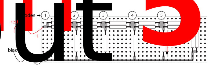
Figure 7:Ladder network including six nodes.
With three extra resistors, it would be possible to extend the ladder network with an extra section. Based on your previous measurements, predict how this would change the voltage on node 6, across the resistor on the right-hand side.
Turn off the voltage source, connect the meter for current measurement, and select the correct meter setting. Ask the TA of your group to check your circuit before you turn the voltage supply back on. Measure the currents through both input wires of the ladder network, and , as indicated in Figure 7. Compare them. Interpret and explain the result of this comparison. Pay attention to the signs of the current values.
Based on the measurements of voltage and current, calculate the equivalent input resistance of the network (use Ohm’s law).
Disconnect the circuit from the power supply. Switch the digital multimeter to the ‘Ohm’ setting and measure the resistance between the input wires. Compare this value with the one you calculated in the previous step. Verify that this is the same value as in Step 6. If the values don’t match, revisit Steps 6 and/or 7, because they should match.
From the voltages measured in Step 3, calculate the current in each vertical branch, such as (see Figure 7), using Ohm’s law for each current. Compare the sum of these currents to the current you measured in Step 5. Verify that these values are the same (except for some measurement error). This is Kirchhoff’s current law in action.
Optional: from Ohm’s law and Kirchhoff’s laws reason what is the equivalent input resistance of the 5-bit ladder network. Compare with the value calculated from the measurements and explain your findings. Hint: call the resistance value , and start combining resistors to equivalent resistances on the right hand of the network.
Optional: from Ohm’s law and Kirchhoff’s laws, reason what is the smallest current in a ladder network with bits.
For more information, see the Wikipedia page on Resistive Ladders.