XCTU Tutorial
Introduction
XCTU is a piece of software developed by DIGI Inc. to configure and test their Radio Frequency (RF) modules, such as the XBee series, through a graphical user interface. This section is a step-by-step tutorial detailing how to navigate the program and use it to configure XBee modules.
Step-by-Step Tutorial
Step 1: Before we begin
Collect the following:
two XBee Modules
two XBee USB Explorer boards
two USB-A to USB-mini cables
a PC or laptop running Windows 10 or higher
XCTU comes installed on the PCs in the Tellegen Hall. If you want to install it on your laptop, you can download XCTU here.
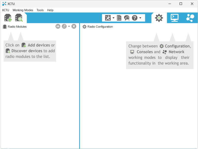
Figure 1:Intro screen of XCTU
Step 2: Discover Devices
Mount each XBee module on an XBee USB Explorer board, and connect both boards to your PC via USB.
Launch XCTU. You should be greeted by the window shown in Fig. 1.
Click on Discover devices to let XCTU detect the connected XBee modules.
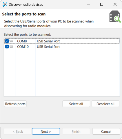
This window shows a list of serial ports. Select all ports to scan them for XBee modules. The ports on your computer should also start with COM but may end in different numbers.
Press Next >.
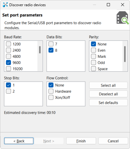
Check if the settings on your screen correspond to the settings in the Figure above. If not, copy them over.
Press Next >.
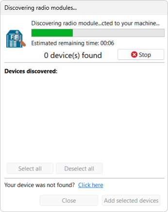
Wait for XCTU to finish scanning for radio modules.
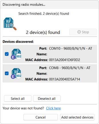
If all went well, you should see two modules in this window. Select both and press Add selected devices.
Step 3: Configuring the Devices
The XBee modules should now be listed under the Radio Modules pane of the main window. Click on the top listed module. You should see a window similar to Fig. 6.
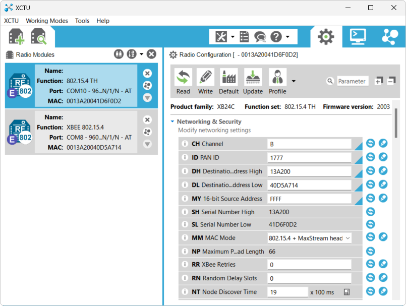
Figure 6:Screenshot of XCTU with the device config page opened
To make# both modules talk to each other, configure both modules as follows. Note that all settings use hexadecimal notation.
CH XBee modules can transmit and receive electromagnetic waves in one of 16 different frequency bands. These bands are commonly called “communication channels.” Radio modules can only talk to each other if they are tuned to the same channel. Set the channel number for both modules to the same number (0-F).
ID The PAN ID (Personal Access Network Identifier) is a number consisting of 4 hexadecimal digits that is unique to your XBee network. Even if XBee modules outside your network are tuned to the same channel, they can only communicate with your modules if they share the same PAN ID. Set the PAN ID for both modules to the same number (0000-FFFF).
To distinguish each individual module in a network, each module is given a unique number called the “address.” Given a transmitted message, the “source address” is the address of the module that transmitted the message. The “destination address” is the address of the intended recipient. XBee modules can have a 64-bit or a 16-bit (source) address:
SH & SL The unique 64-bit serial number of the module. No two modules in the world should have the same serial number. SH represents the most significant 32 bits and SL the least significant 32 bits.
MY A 16-bit local source address. No two modules in the same network should have the same local address.
To configure the modules to use 64-bit addresses:
MY Set the (local) 16-bit source address to FFFF. This number is an exception case that disables the use of 16-bit addresses.
DH & DL These settings represent the destination address of the messages that the module sends. DH represents the most significant 32 bits, and DL the least significant 32 bits. Set DH to the SH and DL to the SL of the other module.
To configure the modules to use 16-bit addresses:
MY Set the (local) 16-bit source address to a number between 0000 and FFFE. Make sure both modules have different source addresses.
DH & DL DH and DL together form a 64 bit number. Because the source address is only 16 bits, the most significant 48 bits are zero. Set DH to 0 and DL to the MY of the other module.
Save the configuration by pressing the Write icon, the green triangles on the right of each setting should turn blue. Both devices are now configured to communicate.
Step 4: Testing the Communication
Click the Consoles Working Mode icon in the top left corner of the program (or press Alt + C). This should result in a window similar to the one shown in Fig. 7. This window allows you to send packets of data between connected modules.
In the top left corner of the terminal window you can see an Open icon. Click the icon to open a connection to the XBee module. Repeat these steps for the other device.
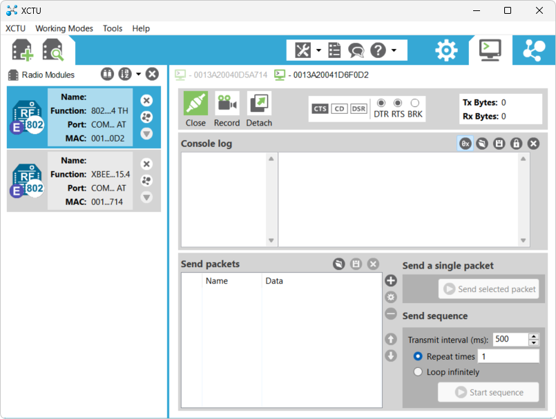
Figure 7:The Console Working Mode of XCTU
Click the + icon on the right of the Send packets pane. The window shown in Fig. 8 should appear.
Specify either a text message (tab ASCII) or a string of hexadecimal numbers (tab HEX).
Click Add packet.
Select your packet in the Select packets pane, and click Send selected packet. The contents of your packet should appear in blue in the Console log, as shown in Fig. 9.
Open the Console Working Mode tab of the receiving module. The sent message should appear in its Console log in red.
Send a different packet back to test the wireless connection in the other direction.
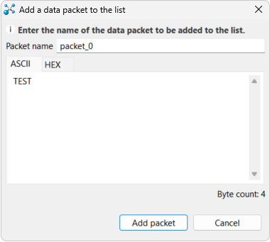
Figure 8:Screenshot of the packet definition dialog
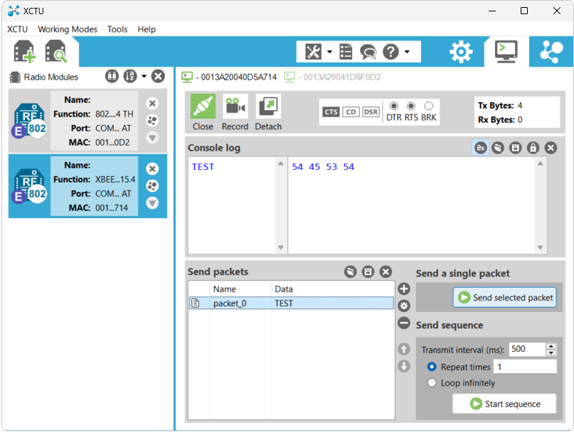
Figure 9:Screenshot of the terminal window after sending and receiving packets