Wireless Communication
Introduction
The robot and the PC require a means to send information to each other. Without a communication link the route planner that runs on the PC is isolated from the rest of the system. To establish one, you are given XBee modules.
XBee modules are a popular brand of wireless communication devices made by Digi International. They communicate with each other using the Zigbee protocol. This is a low-power, close proximity wireless protocol the details of which are outside the scope of this project. The XBee modules communicate with other devices through UART, a serial data transfer protocol that has been explained in the Digital Systems B course. Figure 1 shows the an overview of the communication link between the robot and the PC.
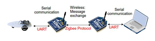
Figure 1:Data transfer path between robot and PC.
Section Establishing an XBee-XBee communication link explains how you can let XBee modules communicate with each other. Section Robot-XBee Integration explains how you can make the robot communicate with an XBee module. And Section PC-XBee Integration explains how you can get a C program on a PC to communicate with an XBee module. You are recommended to follow these sections in order.
Establishing an XBee-XBee communication link
XBee modules are designed fulfill any role in simple and complex communication networks. Because of their versatility, they come with a long list of settings. The network in IP2, however, is as simple as networks can be: two devices communicating through one link. Most settings are irrelevant in this scenario, so we will ignore them.
The XBee modules in the Tellegen Hall are configured in “transparent mode”, in which a module does two things:
If the module receives a byte of data wirelessly with itself as the intended recipient, it it will send a UART message (also called a “data frame”) containing the received byte through its UART transmission (TX) port. The robot/PC can then retrieve the byte of data from this UART frame.
If the module receives a UART data frame on its reception (RX) port from an external device (such as the robot or the PC), it transmits the byte of data encoded in the UART frame wirelessly.
To make the bytes of data contained in the UART frames easier to read, the XBee manuals uses ASCII characters to represent them. For example, the letter “A” corresponds to “01000001”. Not all binary words in the ASCII specification result in visible characters, but this will not be an issue.
If the UART RX port of the XBee module receives the sequence “+++” within one second, the module will enter configuration mode. Once in configuration mode, it will interpret the following UART frames as configuration commands. That is, until it receives the character “” (carriage return, an invisible character), after which the module exits configuration mode.
To establish a communication link between two XBee modules, you need to send a sequence of UART frames to configure each module individually. To automate the bulk of the configuration procedure, we use a program created by the vendor called XCTU. Please go through the XCTU tutorial in Appendix XCTU Tutorial to configure two modules.
Robot-XBee Integration
Creating a SystemVerilog description of a circuit that can (de)serialize UART frames is outside the scope of this course. As such, it has been written for you and you can download it from Brightspace. The port list of the module is as follows:
UART interface:
rxThe port at which the module receives UART frames from the XBee module. This port should be connected to FPGA pin M18.txThe port through which the module transmits UART frames to the XBee module. This port should be connected to FPGA pin N17.
TX user interface:
tx_dataThe byte of data you want to send.tx_validWhen you set this signal high, you indicate to the module that you want to send the byte of data ontx_data.tx_readyWhen this signal is high, the circuit is not busy transmitting data and can transmit new data.
RX user interface:
rx_dataThe most recent byte of data that the module received.rx_validWhen this signal is high, the circuit indicates that it has received a new byte of data.rx_readyWhen you set this signal high, you indicate to the module that you have readrx_data. After that, the module will settx_validlow and it can receive new data again.
The TX and RX user interfaces use a so called ready/valid handshake. This is a commonly used technique to ensure that data isn’t lost when it is transferred between two different systems. Only when the ready and valid signals are both high is data transferred between two circuits.
For more details on the circuitry behind the UART interface code provided on Brightspace, refer to Figure 2 and 3.

Figure 2:Block diagram of the TX stage of the provided SystemVerilog UART interface

Figure 3:Block diagram of the RX stage of the provided SystemVerilog UART interface
PC-XBee Integration
Your C program does not need XCTU to communicate with an Xbee module. It can do so through serial programming. Before writing your own serial interface in C read the Windows Serial Programming tutorial Bayer (2008).
Next, study the template program given in Appendix Serial COM Interface Template in C. Note that similar code is also available on Brightspace (C Library for Communication). The template code consists of 4 functions:
initSio()Initializes the basic file handle to a COM port. (here COM5)writeByte()Writes a single byte to the COM port.readByte()Reads a single byte from the COM port.main()The main function that opens a file handle to the COM port.
At line 6 of the template code you can configure the COM port name and baud-rate:
    #define COMPORT "COM5"
#define BAUDRATE 9600- Bayer, R. (2008). Windows serial Port Programming. http://www.robbayer.com/files/serial-win.pdf