Operational Amplifiers (Op-Amps)
The op amp or operational amplifier can be used to build amplifier circuits. The ideal op amp is treated in the lectures on Electrical Circuits. Anticipating on that the two basic configuration will be discussed here.
An op amp is an IC containing a multistage amplifier with a (+) and a (-) input pin. The voltage difference between those pins is amplified with a very high gain of 105-106. So in first approximation it can be regarded is infinite. This very high gain makes the op amp pretty useless to use on its own since the slightest voltage difference between the input pins will cause the output voltage to clip to either the positive or negative supply voltage. However, by feeding back the output signal to the negative input via a resistive divider (consisting of two resistors), it is possible to control the immense gain of the op amp and to create stable amplifier circuits of which the amplification factor solely depends on the feedback resistors. Figure Figure 1 shows the two basic configurations. For now, please accept that the gain of these circuits can be written as follows:
The non-inverting amplifier with a gain of .
The inverting amplifier with a gain of - (pay attention to the negative value of gain).
You will learn later how to derive these formulas yourself.
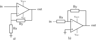
Figure 1:Basic op amp configurations. a) non-inverting amplifier. b) inverting amplifier.
Datasheets
Look up the datasheet of the op amp in the microphone amplifier: the Texas Instruments TL072. You can see that this specific op amp is available in packages with one (TL01), two (TL02), or even four (TL04) op amps in a single package. In the datasheet you can find the pinout of the different packages. With a few exceptions, these pinouts are identical for most single and double op amps in an 8-pin DIL package. The pins 1, 5, and 8 in the single op amp package are sometimes used for specific functions, such as the offset pins in case of the TL071. Note that only some of these pins are used for your circuit.